Introduction
Since ancient times humans have been devising ways to automate laborious and repetitive tasks. There are various examples ranging from ancient history to modern times including water mills for grinding grains, automatic fountains, Johannes Gutenberg’s printing press, James Watt’s steam engine, Ford’s moving assembly line and the Robotic Process Automation. While there exists various types of automated technologies, there is one specific type of automation which has revolutionized our lives i.e a programmed automation. We got the power to instruct the machines for doing a specific task. One of the pioneers was Joseph Marie Jacquard who used punched cards to automate pattern weaving. Since then inventions and innovations have taken place in various sectors.
One sector which adopted this kind of automation is the manufacturing sector. They used Numerical Control to automate the machining process. The instructions are provided to the machines in the form of numbers, letters and symbols. A punched card contains these numbers, letters and symbols. The punched card is inserted into the machine, then the control unit reads and converts the instructions into electric signals. The electric signal is then sent to drive motors which converts these signals into mechanical motion of tool and/or workpiece to perform machining operations. A feedback unit is present in the machine which feeds back the actual movement data to the control unit for correcting errors.
After developments in computer technology, the NC machining process got upgraded to CNC machining process. CNC stands for Computer Numeric Control. CNC machining was developed more than 50 years ago and is used by manufacturers till date.

What is CNC Machining?
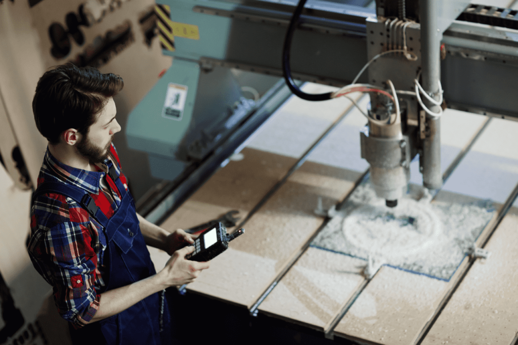
CNC Machining is a process wherein we instruct the plant machinery and tools to perform machining operations in a specific sequence. We provide the instructions through a computer program. This process is a successor to NC Machining wherein we provide instructions through punched cards or magnetic tapes. CNC Machining process involves subtractive manufacturing in which the layers of material are removed from blank/workpiece to produce customized parts.
Framework of the process
How do we achieve this process ?
The framework of this process involves two steps :
- Developing the Computer Program : We need to prepare a set of instructions for the machine. Languages understood by machine are G-Code and M-code.
- Inserting the Program in CNC Machine : CNC Machine reads the instructions from left to right and from top to bottom and then manufactures the product.
Let us understand each step in detail. We will start with the first step.
Computer Program
What is G-Code and M-Code ?
G-Code and M-Codes are AlphaNumeric in nature.
G-Code :
G stands for Geometry. G-Code covers the Geometric and Cutting aspect for the workpiece. G-code tells how the tool/workpiece will perform motion, where it will move. By using G-Code we can specify coordinate systems, we can tell the machine which units to use i.e. English or Metric, we can specify the positioning system i.e. Absolute or Incremental, etc.
By using G-Code, we can achieve the desired geometry from a workpiece.
M-Code :
M stands for Miscellaneous / Machine. M-Code instructs machines to perform Non-Cutting / Non-Geometric operations like – Coolant ON/OFF, Tool Change, Spindle rotation CW/CCW, etc.
Other AlphaNumerals used in CNC Program : G-Code also includes alphanumerals that start with alphabets apart from G. You can find the list here.
Example of the Computer Program :
Let us take an example of drilling a hole. The workpiece is of square shape with dimensions 100 mm x 100 mm x 5mm.As shown in Fig 1. a hole of diameter 10 mm has to be drilled at the center of the workpiece. The coordinates of the workpiece and tool are shown in Fig 1. The workpiece and the tool are at the same height Z=0.

Codes that will be used in program:
The following codes have been taken from Siemens Sinumerik 802d Milling Manual
G71 – Metric dimension data input
G90 – Absolute dimension data input
G94 – Feed in mm/min
M6 – Tool change
G0 – Linear interpolation with rapid traverse
G17 – Selecting X/Y plane
M3 – Rotate spindle clockwise
G1 – Linear interpolation at Feedrate
M2 – End of main program with return to beginning of program
M8 – Start the coolant flow
M9 – Stop the coolant flow
M5 – Stop moving the spindle
Program :
| Block | Specification |
| N010 G71 G90 G94 | This statement tells the machine that we are going to specify all dimensions in mm, we will use absolute positioning and will specify feed rate in mm/min |
| N020 M6 T01 | It tells the machine that we are going to select tool 01 |
| N030 G0 X150 Y50 Z 50 | It tells the tool to travel in a linear manner with the fastest speed to the target coordinates |
| N040 G0 Z20 | – |
| N045 G17 | It tells the machine that we are going to perform drilling in X/Y plane |
| N050 M8 M3 S400 | It tells the machine to switch on the coolant, tells the spindle of tool to rotate clockwise with a speed of 400 rpm |
| N060 G1 Z-60 F15 | It tells the tool to travel in linear manner at a rate of 15mm/min to the target coordinates |
| N070 G0 Z20 | – |
| N080 M9 M5 M2 | It tells machine to switch off the coolant, stop the rotation of spindle and end the program |
Programming Methods :
1. Manual Programming :
The programmer has to visualize the machining operations that will be carried out on the workpiece in a sequence. Then the programmer has to manually develop the program i.e. without taking help from the computer.
2. Conversational Programming :
Conversational Programming allows operators to generate programs on a CNC machine control. The operator answers a series of displayed questions about the intended workpiece. The questions include type of material, OD/ID dimensions, part lengths,etc. After the questions are answered, the control generates the program. Conversational Programming can be done either on a shop floor or on a personal computer.
3. Use of CAD/CAM systems:
The programmer uses CAD (Computer-Aided Design) software and CAM (Computer-Aided Manufacturing) software in a sequence.
First, the programmer creates a CAD model of the part that has to be manufactured. Then the programmer has to transfer this model to the CAM software. If the programmer has CAD and CAM as different packages then the programmer has to import CAD files into the CAM software. If the programmer has CAD and CAM integrated in a single package then there is no need to import or convert CAD files.
Second, the programmer has to enter the details of machining operations, select tools and enter tool data in CAM in order to generate a toolpath. Toolpath is the path that cutting tool will follow to machine the part. Once the toolpath is generated, the programmer can run the simulation to do collision checks. Once the toolpath is finalized, the programmer uses a Post Processor to generate the program. The role of the post processor is to read the toolpath data and convert it into a program that can be read by a machine controller.
The program can be transferred to a CNC machine controller using data carriers such as a USB.
To see Pros and Cons of each method, visit What CNC programming style best suits your operations?
CNC Machine
Let us understand the elements of a CNC machine and how it works.
Elements of a CNC machine :
The main components of CNC machine are:

1. Input Devices:
The below devices are used to transfer programs to the CNC machine.
- Floppy Disk: It is a small magnetic storage device. Floppies are sensitive to large magnetic fields, dust and scratches. Floppies can degrade fast and might be unreadable after only 3 years.
- USB flash drive: It is a removable and rewritable hard drive. It is portable and compact in nature and has more storage size than a floppy disk.
- Serial communication: The data transfer can be accomplished through a serial communication port. The port is built on RS-232 standard.
- Ethernet: The program can be transferred from the computer to CNC machine via ethernet communication cable. Most companies built LAN as their infrastructure.
- Wireless: The program can be transferred to a CNC machine via Wi-Fi.
2. Machine Tool
A machine which satisfies below conditions is known as a machine tool.
- It is power driven
- It is non-portable
- It has sufficient value in terms of capability and performance
- It has a cutting tool that performs machining operation on workpiece
- It can perform more than one type of machining operations
It is a place where a workpiece is converted into a finished product.
Examples of machine tools include lathe machines, milling machines, etc.
Machine tool consists of a worktable, spindle, motors, cutting tools, work fixtures and other equipment that assist in machining operation.
3. Drive System
The drive system is used to provide controlled motion to elements of CNC machine tools such as work-table, tool spindle, etc. The drive systems used in CNC machine are:
a. Feed Drive:
Feed Drive is used to control the position and velocity of the slide or table of a CNC machine. Feed Drive is used to provide linear motion to a workpiece or tool.
Feed Drive consists of a motor coupled with a mechanism. Motor provides rotary motion and the mechanism converts rotary motion into linear motion. An example for the motor is a servo motor and for the mechanism is a ball lead screw. A schematic of Feed Drive is shown below

b. Spindle Drive:
Spindle Drive provides cutting power that is required for machining the workpiece. The cutting power is generated through angular motion of the workpiece or tool.
Spindle Drive consists of a spindle motor which provides angular motion to the spindle. Spindle transfers angular motion to the workpiece or tool as they are attached to the spindle. A schematic of Spindle Drive is shown in Fig 4.

4. Feedback System
It is used in closed loop CNC machines. This system is used to send actual position and actual velocity data to the MCU. The data is used to correct the error between the specified value and actual value.
The devices that can be used to measure position are encoders and linear transducers. The device that can be used to measure velocity is the tachometer.
5. Machine Control Unit (MCU)

6. Display Unit
It is an interactive device between operator and machine. It displays data such as position status, spindle rpm, feed rate, part programs, etc.
How does a CNC machine work?
MCU converts the entered program into electrical signals and sends it to the amplifier to drive the motor. The motor operates the machine tool components to perform the cutting actions and other auxiliary functions. Feedback systems monitor the actual output and it sends the data to MCU. MCU calculates the error. If there is any error, MCU generates electrical signals for the motor and eliminates the error.
Materials that can be used for CNC Machining
1. Metal
Below is a list of some of the metals and some of the variants which can be machined on CNC.
2. Ceramics
Ceramics like zirconia can be CNC machined for dental applications.
3. Glass
Operations like engraving, bevelling, grinding, drilling, milling and polishing can be done on glass using CNC. The Optical Industry has used CNC for machining glass.
4. Plastic
Machining plastics is not the same as machining metals. One of the challenges is heat buildup. Machining involves friction and thus heat is generated. If the heat is not controlled during the machining process it can cause changes in tolerances, can reach a softening point of plastic and in case of thermosets it can burn the surface. Another challenge is performing milling operations on plastic. The vibration of the component during operation can leave chatter marks on the component. CNC routers have vacuum chuck as a workholding device.
Using machining operations for plastic has advantages. CNC Machining eliminates the need for mold and thus it reduces cost and startup times. Some materials such as PTFE and UHMW are not possible to mold and require machining.
Plastics that can be used for CNC machining are Acrylic, PVC, PMMA, Nylon, ABS, POM, PTFE, HDPE and PEEK.
5. Composites
Composites can be machined on CNC. The nature of composite materials poses a challenge for machining operations. Composites are made up of matrix and fibre. The matrix has low thermal conductivity and the fibres are abrasive. This poses a challenge in tool design. Heat is not transported away from the cutting edge and fibres can cause rapid tool wear. Cutting performance depends on both tool geometry and tool material. Selection of improper tools can cause delamination, inconsistent cut geometry, hole exit deburring and rapid tool wear.
To tackle the challenge, three different materials can be used for composite tools. They are Carbide, Coated Carbide and Polycrystalline Diamond (PCD). The tools used for composites are often custom products.
The machine tool required to produce contoured shape on composite material is generally a 5-axis machine tool.
The most widely used material is CFRP (Carbon Fiber Reinforced Plastic). Panels made up of aluminum composites like Dibond can be used for CNC Machining.
Factors affecting cost of CNC Machining
1. Material
Cost will depend on:
- Raw materials: It includes the cost of raw material itself. The availability of raw material is also a factor that affects cost. Hard to find materials will be more expensive than materials that are easily available. Machinists buy material in blocks and they will charge for the whole use of a block. Customers must try to fit as many parts as they can in a block. Use of fewer blocks can save money in the long run.
- Machinability: Materials that have low machinability will take more time and effort to machine. Apart from time and effort, these materials also consume cutting fluids, electricity and cutting tools. Materials that have high machinability can be machined faster.
Additional measures: If the material poses some hazard, then additional measures will be taken. An example is machining of composites. During machining, plenty of dust is raised. The dust can pose health hazards and can damage machine controllers and equipment. To control this dust a suitable cartridge style dust collector is installed. Such additional measures will add to the cost.
2. Manufacturing equipment
Shops set an hourly rate for running the machine. This rate depends on:
- The number of axes.
- Operations to be performed. Ex: drilling, milling, etc.
- The number of machines used i.e one or more than one.
- Capability and size of the equipment.
- Cost of cutting tools.
3. Tolerances
Tighter tolerances can add up to the cost of CNC machining. Tighter tolerance requires more time and more effort to produce the part. It also demands better quality control equipment for inspections. Tighter tolerance will decide which tools, machines and cutting techniques to be used for manufacturing the part.
Tolerance must be provided for appropriate features only. Ex: mating areas. If tolerance is provided to every dimension, cost will increase due to increase in setup time, modification in computer programs and due to scraps and rework.
4. Quantity of parts
The operator requires time to set-up the machine for manufacturing the part. This setup cost will be fixed irrespective of quantity. Same setup cost can be assigned to single quantity as well as bulk quantity. If we order in bulk, the overall cost will increase but the cost per part will reduce. Also, if we order in bulk, the machine shop can buy bulk raw materials at a better price.
5. Labour
Though CNC is automated, manual intervention is required for below tasks.
- Design: Labour cost is involved if we outsource the task of preparing 3D models or CAD files of the part. This cost can be eliminated by preparing the CAD file on our own.
- Programming: The manufacturing engineer checks the design and gives suggestions. Then the programmer prepares the computer program.
- Setup: The operator has to load tools into the tool changer, set up the machine and the workpiece.
- Post processing: It involves cleaning, support removal and assembly of parts.
6. Design
Complex features such as non-standard hole sizes, lettering and thin walls can add up to the cost of CNC machining. Complex features take more programming time, demand specialized tools and multiple setups to manufacture a part. Increase in runtime will increase cost.
By eliminating unnecessary features, we can simplify the design. Wherever possible, we can choose recessed texts instead of raised texts. For thin walls, a good rule of thumb is a width-to-height ratio of 3:1. Machining for walls can be made easier by adding a draft of angle 1, 2 and 3 degrees.
7. Additional treatments
These treatments include surface finish operations that will be performed on the machined part. A number of finishing operations can be used to improve surface roughness, aesthetics and wear resistance.
Some of the finishing operations are:
- As machined: This finish can have minor visible tool marks. The part is provided with a specific surface roughness value. These values are planned in advance and are regulated by industry standards. The values typically specified for CNC machining are 3.2 μm Ra, 1.6 μm Ra, 0.8 μm Ra and 0.4 μm Ra. The lower the Ra value more effort and quality control is required and hence the cost will increase. As machined parts have tighter dimensional tolerances.
- Bead Blasting: It provides uniform matte surface finish to the machined surface. Bead blasting is a manual process. It can be used in applications where dimensional tolerance is not a key concern.
- Anodizing: Anodizing type II is used for making aesthetically pleasing surfaces. Anodizing type III produces thick coatings that provide excellent corrosion and wear resistance. Type III requires closer process control. Hence the cost is higher than type II.
- Powder Coating: It is used for applications where high impact strength is required. These additional treatments will also add up to the overall cost
List of leading CNC machine tool manufacturers
- Okuma Corporation
- Siemens
- Haas Automation Inc
- DMG MORI
- Yamazaki Mazak Corporation
- Doosan Machine Tools
- Chiron Group
- HURCO
- Makino
List of CNC machine tools
- Lathe Tool
- Milling machine
- Swiss style turning tool
- Turn-Mill Centers
- Shaper
- Router
- Plasma Cutter
- Electric Discharge Machine
- Laser Cutter
- Grinders
- Water Jet
Benefits of using a CNC Machine
1. Quality of parts
Since CNC is computerized, human error is eliminated. CNC machines manufacture parts with high precision and accuracy. The two copies of a part will be virtually identical with an average variation of 0.020mm. That means CNC can replicate products with uniformity.
2. Safety
The operator is at a safer distance from the machine. The machines work behind a guard or a closed transparent safety door.
3. Less material waste
It uses as much raw material as necessary. Hence, waste can be reduced.
4. Lowers the cost of production
One trained worker can monitor the output of several CNC machines. Thus the amount of labour is reduced. Also, CNC machines can work faster and operate 24/7 as opposed to traditional machining where operators can develop fatigue. CNC machines are stopped only for maintenance purposes.
5. Complex Shapes
CNC machines enable production of complex shapes that were earlier not possible to produce using traditional methods.
Conclusion
CNC machining has advantages over traditional machining. Manufacturers who are still using traditional machining can think of using CNC machining to increase their productivity.
Alternatives to CNC Machining
Every application is different. There are alternatives to CNC machining which may prove more economical for specific applications.
1. Additive Manufacturing
It is an opposite process to CNC machining. The process takes a layer-by-layer approach where the successive layers of material are added to create the required object. Within additive manufacturing, seven different technologies are available to manufacture a product
2. Molding and Casting
If we want to replicate an object, mold and cast can be used.
Mold: A mold is an impression of an object. The mold is hollow in nature. The process of preparing mold is known as molding.
Cast: After the mold is prepared, a material (in liquid form) is poured into the hollow cavity of the mold. The liquid is allowed to solidify. Upon solidification, the material becomes a replica of the object. This process is known as casting.
3. Forming Process
In this process, the workpiece/raw material is converted into a desired product by changing the shape/form of the workpiece. The shape can be changed by applying stresses such as tensile, compressive, bending, shear, etc. During this process material doesn’t lose its mass but only its form.
Forming Process includes sheet metal fabrication, forging, pressing and extrusion.
4. Joining Process
This process is used to join two or more parts. Joining process can be used to create assemblies.
Joining process includes mechanical fastening, welding, brazing, soldering and adhesive bonding.
Karkhana.io – Your Ally for On-demand, CNC Manufacturing
Karkhana.io is India’s foremost on-demand manufacturing company. We partner with start-ups, small & medium enterprises and large businesses, and address their prototyping and mass production requirements. We have a large number of trusted vendors with manufacturing capabilities spanning 3D printing services, vacuum casting, sheet metal fabrication, CNC machining, and injection molding.
Our network of CNC machining facilities can produce complex prototypes and low-volume production as well as high-volume production runs of precision machined parts. We help clients with selecting the right material and providing the best way to optimize the design. We work with a large network of manufacturers that together have over 100+ professional machines. Therefore, we can fulfill both high-volume and low-volume production requirements, and we offer competitive pricing.
Hence, if you are searching for a partner to help you with your CNC machining requirements, reach out to us!
Image ref:
https://www.freepik.com/photos/business”>Business photo created by pressfoto – www.freepik.com
